Contech-lighting TLTO12V2 16CR Manuel d'utilisateur
Naviguer en ligne ou télécharger Manuel d'utilisateur pour Pour la voiture Contech-lighting TLTO12V2 16CR. ConTech Lighting TLTO12V2 16CR User Manual Manuel d'utilisatio
- Page / 1
- Table des matières
- MARQUE LIVRES
Noté. / 5. Basé sur avis des utilisateurs
TLTO INST
For ConTech Lighting OutdoorTapelight Series: White, Single Color, and RGB
www.contechlighting.com All specifications subject to change without notice.1-847-559-5500
This document can be recycled.
INSTALLATION PROCEDURES
• It is recommended to layout the system before permanently installing the adhesive backed
LED tape.
• Ensure that the power supply is sized properly for LED tape loading otherwise power supply
or LED tape may be damaged. Example: the High Output Outdoor LED tape consumes
1.8Ws per foot. This means that a 36W power supply can effectively drive 20-feet of LED
tape (36 ÷ 1.8 = 20). Review the loading chart to determine power supply maximum load
run length capabilities.
• Locate position for power supply and install in accordance with the National Electrical Code
(NEC) and local codes. Review the loading chart to determine the maximum system run
length; Refer to wiring chart or power supply distance from first LED tape section to
minimize the effects of voltage drop.
A. PLUG-IN STYLE: Class 2, 120V input with 12V secondary. Install away from heat sources.
• The LED tape can be field cut at marked cut lines only, every 4". One cut per reel. Cutting
the tape terminates the conductivity of the tape.
• At the cut end, apply silicone sealant (provided) to the tape and cover with an end cap
(provided).
MOUNTING
• Clean mounting surface to ensure proper adhesion of LED tape.
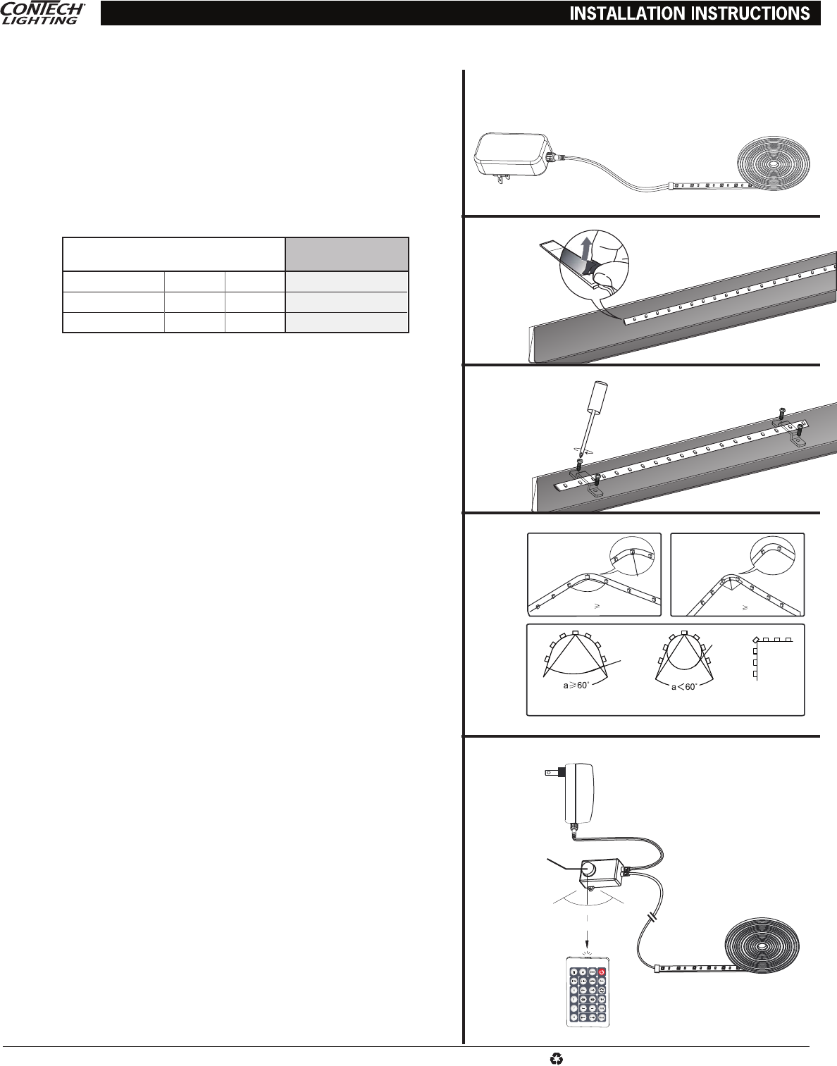
• Measure the desired space for the LED tapelight installation; cut tape accordingly. Note that
the LED tape, adapter and infrared receiver (on the RGB tape) are pre-assembled. (Figure 1)
• Install the tapelight by either:
A. Carefully pressing the LED tape onto mounting surface. Do not apply excess pressure.
Avoid contact with LEDs. (Figure 2)
B. Place the LED tape into the desired position and use the mounting clips and screws
provided to secure into place. Recommended maximum distance between mounting clips
is 24" for most applications. (Figure 3)
• Do not pinch or bend LED tape and connectors at hard angles. Bend only between LEDs.
Use an angle greater or equal to 90° when there is an LED chip on the corner while placing
the tape in a concave position. Use an angle greater or equal to 60° when there is no LED
chip on the corner while placing the tape in a concave position. Use an angle greater or
equal to 60° when there is an LED chip on the corner while placing the ape in a convex
position. In the convex position, the angle should not reach 90°. (Figure 4)
RGB CONTROLLER
• Install the Infrared receiver (Figure 5). Either remove the protective tape from the adhesive
back of the infrared receiver, then place the infrared receiver into position and press to
ensure a proper adhesion to the surface; or use the two screws to install the infrared
receiver into desired position.
• When using the remote, the infrared receiver should face the remote. Sensor efficiency
distance ≤16.5 feet and sensor efficiency angle about 60°
POWER SUPPLY
• Connect adapter to power outlet
• WARNING: If using the adapter outdoors where it could be exposed to rain, snow, or solid
objects less than 1mm, to protect against electric shock, install the adapter only to a
receptacle that has a weatherproof enclosure.
• WARNING: Risk of electric shock. Mount the adapter at a height 12" or greater from the
ground surface.
• The LED strip and infrared receiver can be used outdoors but are not submersible.
IMPORTANT SAFETY INSTRUCTIONS:
• Read all the instructions before installation. Save instructions for later use.
• Turn off power at fuse or circuit breaker box before installation or before doing any maintenance work.
• Product must be grounded to avoid potential electric shock and any other potential hazards.
•
Product must be mounted in locations and at heights and in a manner consistent with its intended use, and in
compliance with National Electrical Code and local codes. Use of accessory equipment is not recommended.
• Installing contrary to instructions may cause unsafe conditions.
• Do not block light from the trim aperture, in whole or in part, as this may cause unsafe conditions.
• Warning: Risk of fire. Most dwellings built before 1985 have supply wire rated at 60°C. Consult a qualified
electrician before installation.
• To avoid hazards to children, account for all parts and properly dispose of all packing materials.
• Call the Technical Support department at ConTech Lighting with any installation questions: 847.559.5500.
1. Distance from first LED tape section to end of LED tape run. Exceeding this length
may result in inconsistent light output from beginning to end of the LED tape run.
ConTech POWER SUPPLY
INPUT VOLTAGE: 12V DC
OUTDOOR
WATTS PER FOOT: 1.8
MODEL NO. TYPE WATTAGE MAX LOAD
1
TLPO12VP36 Plug-In 36W 20 ft.
TLPO12VP60 Plug-In 60W 33 ft.
1
2
3
4
5
LED Chip
Correct lncorrect lncorrect
Angle 90
o
Angle 60
o
Adapter
Infrared receiver
60°
10' 10'
≤ 16.5'
1
Résumé du contenu
Page 1 - POWER SUPPLY
TLTO INSTFor ConTech Lighting OutdoorTapelight Series: White, Single Color, and RGBwww.contechlighting.com All specifications subject to change without
Produits connexes et manuels pour Pour la voiture Contech-lighting TLTO12V2 16CR
 (1 pages)
© 2020, manymanuals.fr. Tous droits réservés | 0.999 s |
 Manymanuals.com
 Manymanuals.de
 Manymanuals.fr
 Manymanuals.it
 Manymanuals.pl
 Manymanuals.cz
 Manymanuals.es
 Manymanuals-pt.com
Commentaires sur ces manuels